

Ideal timing for the opening and closing of the inlet and outlet valve which in turn protect the engine from defects like knocking or detonation.Provide the exit for the combustion residual so that the next cycle of the engine can take place.Provide engine with a mixed air and fuel or air in case of diesel engine when required ( at the time of suction) which is the necessity of the engine.Complete seizure of the combustion chamber at the instant at which the combustion of air-fuel mixture takes place as the leakage can cause damage to the engine and can be hazardous.Synchronization between the steps of a cycle of the engine from the intake of air-fuel ratio to the exhaust of the combustion residual.

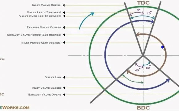
The normal engine completes around 100000 cycles per minute, as we know there are number of processes involved in a single cycle (from the intake of the air-fuel mixture to the exhaust of the combustion residual) of an internal which makes it necessary to be equipped with an effective system that can enable The valve timing diagram comprises of a 360 degree figure which represents the movement of the piston from TDC to BDC in all the strokes of the engine cycle, Which is measured in degrees and the opening and closing of the valves is controlled according to these degrees. We always discuss “The air fuel mixture combust to cause the movement of the piston which in turn causes crankshaft rotation” also “The residual of the combustion goes out from the exhaust” but have you ever wonder, How does this intake and exhaust occurs?, How the timing of this intake and exhaust is controlled? The answer is intake and exhaust valve, right? But the question arises, How these intake and exhaust valve is controlled? Let’s just dig it out.Ī valve timing diagram is a graphical representation of the opening and closing of the intake and exhaust valve of the engine, The opening and closing of the valves of the engine depend upon the movement of piston from TDC to BDC, This relation between piston and valves is controlled by setting a graphical representation between these two, which is known as valve timing diagram.


 0 kommentar(er)
